A Geotextile Tube is a large, permeable textile container used to dewater and contain dredged sediment, sludge, or industrial by-products. It looks simple from a distance. Its performance depends on careful engineering.
The process begins when a slurry is pumped into the tube. Water passes through the fabric pores, while solid particles remain inside. Gravity then helps the retained material settle and consolidate. As the water leaves, the tube becomes firmer and more compact. This can reduce transport volume and create a manageable containment structure.
Dr. Jorge G. Zornberg, a recognized geosynthetics researcher, has stated, “Geosynthetics should be viewed as engineering materials, not merely construction products.” This perspective matters here. Fabric strength, pore size, seam quality, polymer selection, and site preparation all influence results. A weak foundation may cause settlement or sliding. Poorly chosen fabric may release fine particles too quickly or drain too slowly.
In practice, engineers often test the actual slurry before full-scale filling. Small samples reveal whether the material will dewater effectively. Field crews also inspect pumping pressure, tube height, anchoring, and nearby drainage paths. These details are easy to overlook.
The method is efficient, but not automatic. Weather, sediment chemistry, and loading conditions can change performance. A Geotextile Tube may appear stable while internal consolidation continues. That uncertainty deserves monitoring, not guesswork.
This introduction examines what a Geotextile Tube is, how its filtration process works, and why design judgment remains essential.
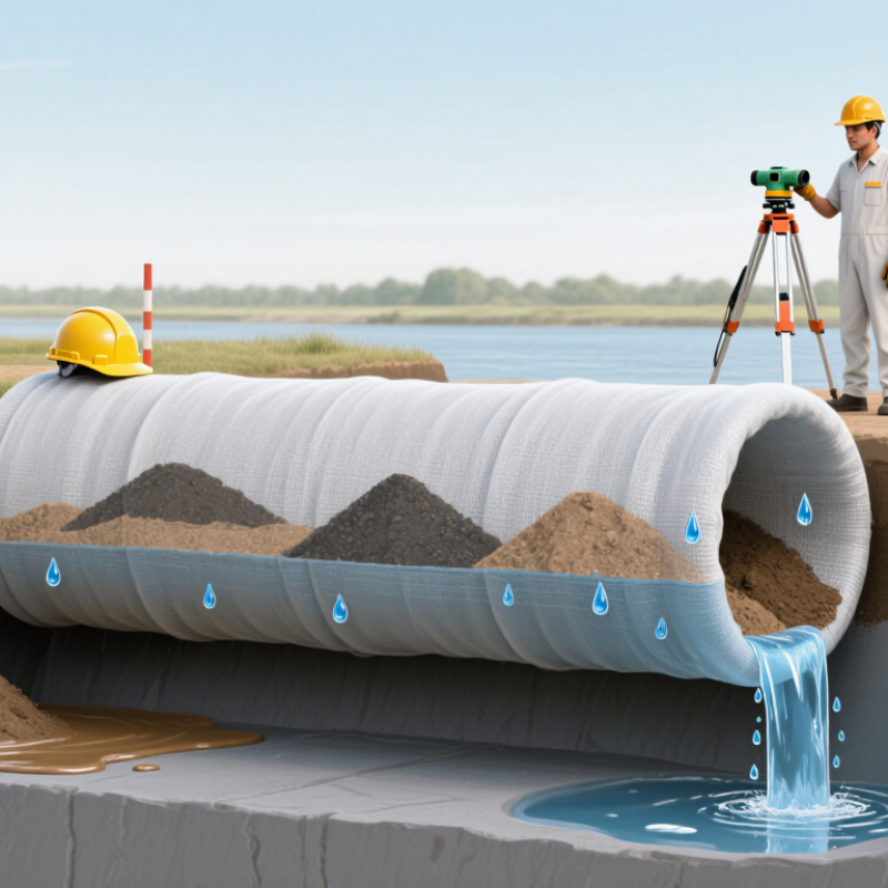
A geotextile tube is a large, permeable fabric container used to manage dredged sediment, sludge, or other water-rich materials. A pump fills the tube, while water passes through tiny openings in the fabric. The remaining solids gradually consolidate inside.
Its structure usually combines strong woven geotextiles with carefully designed seams. Woven yarns create a stable grid that resists stretching under hydraulic pressure. Depending on the fabric type and test direction, tensile strength can exceed 100 kN/m. That number matters. It indicates strong resistance to pulling, but it does not describe every installation condition.
During filling, the tube may look soft and oversized. Later, drainage reduces its volume, and the trapped material becomes denser. Site teams should monitor fill height, outlet clarity, seam behavior, and nearby ground movement. A fabric with high strength can still perform poorly if the foundation settles unevenly or the tube faces sharp objects. Testing also matters, because machine direction and cross direction may show different results.
Field inspections often reveal small issues early. A blocked outlet can slow dewatering. Excessive pumping can stress seams. Sun exposure may weaken uncovered fabric over time. These details are easy to overlook. The 100 kN/m figure should support design decisions, not replace them. Engineers still need project-specific testing, drainage calculations, and inspection records before installation.
What Is a Geotextile Tube and How Does It Work?
A geotextile tube is a permeable fabric container for dredged sediment, sludge, or industrial solids. Pumped material enters the tube, while water drains through microscopic fabric openings. The retained solids form a gradually strengthening filter cake. Flocculants make this separation faster. They bind fine clay and organic particles into larger flocs, allowing water to escape more easily. The fabric decides.
With the correct polymer and dosage, reported applications can achieve up to 95% solids capture. However, this figure is not automatic. The U.S. EPA’s 2006 Biosolids Technology Fact Sheet identifies polymer conditioning as a major factor in improving dewatering and solids retention. USACE Engineering Manual EM 1110-2-5025 also stresses site-specific testing for dredged-material treatment. In practice, operators should measure filtrate turbidity, suspended solids, cake dryness, and polymer consumption.
A jar test usually comes before full-scale pumping. Technicians mix several flocculant concentrations with representative slurry, then observe floc size and settling speed. Too little polymer leaves cloudy filtrate. Too much creates weak, slimy flocs and raises operating costs. That mistake is common. Slurry chemistry can change after rainfall, seawater intrusion, or excavation of new layers. A 95% capture rate may therefore describe one tested condition, not every operating day. Careful sampling and repeat trials make the result more credible.
Geotextile tubes dewater sludge by allowing water to drain through a permeable fabric while retaining larger solids. Flocculants bind fine particles into larger agglomerates, improving filtration and enabling solids capture of up to 95% under optimized operating conditions. Actual performance depends on sludge characteristics, polymer selection, dosage, and fabric properties.
A geotextile tube is a large, permeable fabric container used to dewater slurry. During pumping, a mixture of water and fine solids enters the tube through a controlled inlet. Water passes through the fabric pores, while solids remain inside and form a denser mass. The fabric must withstand filling pressure, uneven loading, and movement around the inlet area.
ASTM D4595 evaluates the tensile properties of geotextiles using a wide-width strip specimen. Technicians clamp the sample and pull it until failure. They record tensile strength and elongation in both machine and cross-machine directions. These results help engineers judge whether the fabric can resist stretching during slurry pumping. However, this laboratory test does not reproduce every field condition. That distinction matters.
A reliable design compares the ASTM D4595 results with expected pumping pressure, tube dimensions, slurry density, and installation conditions. Seams, lifting points, and inlet connections also need separate attention. In field reviews, uneven filling often creates more stress than expected. Small wrinkles can become weak zones. Careful monitoring helps, but it cannot replace suitable testing. A conservative design leaves room for uncertainty, especially when solids settle faster than planned or pumping becomes irregular. Mistakes happen. The goal is to limit their consequences.
A technical overview of the first operating step, the role of geotextile confinement, and the tensile-strength properties evaluated using the ASTM D4595 wide-width strip method.
| Data Dimension | Technical Data | How It Applies to Slurry Pumping | Measurement or Design Reference |
|---|---|---|---|
| Geotextile tube | A permeable tubular containment structure manufactured from high-strength geotextile fabric. | It receives dredged sediment, industrial sludge, or other pumpable solids and retains the solids while allowing water to drain through the fabric. | Tube dimensions, fabric type, seam construction, and inlet arrangement are selected for the specific material and site conditions. |
| Step 1: slurry pumping | The prepared slurry is transported through a pipeline and discharged into the tube through an inlet port. | Controlled filling helps distribute solids inside the tube and limits localized loading, excessive bulging, and unstable stacking. | Pumping rate, solids concentration, inlet pressure, discharge location, and fill sequence should be established through project testing and engineering review. |
| Slurry composition | A mixture of water and suspended solids, such as silt, clay, sand, or dredged sediment. | Particle size, organic content, viscosity, and solids concentration influence dewatering speed, filter performance, and the final retained volume. | Representative samples should be tested before full-scale filling; no single solids concentration is suitable for every application. |
| Primary dewatering mechanism | Water passes through the geotextile while the larger solid particles are retained. | Initial drainage reduces free water and lowers the volume of the contained material. Further consolidation occurs as the material settles and compresses. | Performance depends on fabric apparent opening size, permittivity, soil gradation, clogging behavior, and the chemistry of the slurry. |
| ASTM D4595 purpose | Wide-width strip tensile test used to determine tensile properties of geotextiles. | The test provides tensile strength and elongation information that supports evaluation of the fabric’s resistance to pulling forces during filling, handling, and service. | ASTM D4595 evaluates tensile properties in the machine direction and cross-machine direction using a wide strip specimen. |
| Test specimen width | ASTM D4595 is commonly known as the 200 mm wide-width strip method. | The wide specimen reduces the influence of individual yarns and provides a more representative measurement of the geotextile’s in-plane tensile behavior. | Laboratory preparation, specimen conditioning, gripping, and test details must follow the applicable edition of ASTM D4595. |
| Reported tensile properties | Peak tensile force, tensile strength normalized by width, and elongation at maximum force may be reported. | These values help engineers compare the fabric’s capacity with expected stresses from filling, self-weight, settlement, handling, and site-specific loading. | Results should be reported separately for the machine and cross-machine directions; seam strength may require a separate evaluation. |
| Machine direction | The principal direction in which the geotextile was manufactured. | Directional strength differences can affect tube orientation, seam layout, lifting, and resistance to longitudinal stresses. | ASTM D4595 testing should identify the direction of each specimen and report directional results separately. |
| Cross-machine direction | The direction perpendicular to the machine direction within the fabric plane. | This direction can be important for circumferential stresses caused by internal filling pressure and the tube’s expanding profile. | Design checks should consider the weaker principal direction rather than relying only on a single average tensile value. |
| Fabric tensile strength versus tube capacity | Fabric tensile strength is a material property; the capacity of a finished tube also depends on geometry, seams, installation, and loading. | A high fabric tensile value alone does not establish the allowable fill height, operating pressure, or overall tube capacity. | Use project-specific calculations and, where appropriate, seam tests, hydrostatic tests, and field monitoring in addition to ASTM D4595 data. |
| Filling control | Progressive filling with observation of the tube profile, inlet conditions, and drainage behavior. | Controlled operation helps prevent overfilling, uneven settlement, abrupt pressure changes, and damage at connections or seams. | Follow the engineered fill plan and manufacturer-independent project specifications; stop or adjust pumping if unsafe deformation or leakage is observed. |
| Post-pumping transition | After pumping, free water continues to drain and the retained solids consolidate. | The tube becomes more stable as water leaves and the solids gain density, but the final volume and strength develop over time. | Monitor settlement, drainage, surface condition, and surrounding areas before cutting, stacking, covering, or beneficially reusing the dewatered material. |
Technical note: ASTM D4595 verifies tensile properties of the geotextile material; it does not by itself certify a complete geotextile-tube system or define a universal pumping rate, fill height, or allowable pressure. Final design values should be based on the applicable ASTM edition, project testing, site conditions, and an engineering assessment.
A geotextile tube separates water from suspended solids through a woven or nonwoven fabric shell. During dewatering, liquid moves through the fabric while sludge particles remain inside. Filtration performance depends heavily on the fabric’s apparent opening size, or AOS.
ASTM D4751 measures AOS by passing calibrated glass beads through a geotextile sample. The test identifies the opening size related to the bead size that passes through the fabric, commonly reported as O95. A smaller O95 generally retains finer particles. However, AOS is not the same as a perfect pore-size measurement. Fabric structure, testing conditions, and particle shape can influence the result.
A practical design review should compare O95 with the actual sludge gradation. Water chemistry, solids concentration, and pumping pressure also matter. Field operators often observe a filter cake forming on the tube surface. This cake can improve solids retention, but it may slow drainage. That behavior is easy to underestimate.
A small detail matters. ASTM D4751 evaluates the geotextile under controlled laboratory conditions, not the entire tube system. It cannot fully predict clogging, blinding, or long-term flow reduction. Engineers should combine the AOS result with permeability data, retention testing, and representative slurry trials. Choosing fabric from O95 alone may appear efficient, yet it can produce disappointing dewatering performance when the sludge contains irregular or very fine particles.
A geotextile tube dewaters dredged sludge through filtration and gravity. During Step Three, free water drains through the fabric pores. Solids remain inside the tube. The material slowly changes from a liquid mixture into a firmer soil mass. Typical volume reduction reaches 20–50%, according to data summarized in U.S. Army Corps of Engineers dredging guidance and geosynthetic dewatering case studies. Actual results depend on solids content, polymer selection, fabric permeability, and filling cycles.
A 10,000-cubic-meter slurry may therefore lose 2,000–5,000 cubic meters of water. That difference can reduce hauling loads and improve site storage. Operators should not treat the range as guaranteed. A fine clay slurry may drain slowly and retain more water. Field testing is essential. The Water Environment Federation recommends evaluating sludge characteristics before selecting a dewatering process. In practice, even a well-designed tube can underperform when feed concentration changes unexpectedly.
Tips: Collect a representative sample before full-scale filling. Test several polymer doses, not just one. Place the tube on a level, drained foundation. Measure filtrate clarity, cake height, and daily volume loss. Keep records with photographs and rainfall notes. This sounds basic, but poor monitoring often creates the biggest uncertainty. Allow consolidation time after filling; the final volume may continue decreasing for weeks.
It holds dredged sediment, sludge, or other water-rich solids. A pump fills the fabric container. Water drains through tiny openings, while solids remain inside.
It shows strong resistance to pulling. It does not guarantee safe performance everywhere. Test results may differ between machine and cross directions.
Uneven foundation settlement can distort the tube. Sharp objects may damage the fabric. Excessive pumping can also stress the seams.
Flocculants bind fine particles into larger groups. Water then escapes more easily. Some tested conditions achieve up to 95% solids capture.
No. It depends on slurry chemistry, polymer dosage, and fabric performance. Rainfall or seawater intrusion can change the result. The estimate can be wrong.
Technicians test several flocculant concentrations before full-scale filling. They observe floc size and settling speed. Too little creates cloudy filtrate. Too much may create weak, slimy flocs.
Typical reduction ranges from 20% to 50%. A 10,000-cubic-meter slurry may lose 2,000–5,000 cubic meters of water. Fine clay may drain more slowly.
Check fill height, outlet clarity, seam behavior, and nearby ground movement. Record cake height and daily volume loss. Photograph conditions after rainfall.
Use a level, well-drained foundation without sharp objects. Uneven support increases local stress. That assumption needs checking before filling.
No. Consolidation may continue for weeks. The tube may look oversized at first, then become denser. Operators should allow extra time for final volume changes.
A Geotextile Tube is a large, permeable textile container designed to separate solids from water in slurry. Its structure commonly uses woven geotextiles, which can provide tensile strength exceeding 100 kN/m and withstand the pressure created during filling. The process begins with slurry pumping, where the tube receives a mixture of water and solid particles. ASTM D4595 can be used to verify the tensile strength of the textile and confirm its ability to resist loading.
After filling, filtration takes place through the fabric. Flocculants help bind fine particles together, enabling solids capture of up to 95%, while ASTM D4751 measures the material’s apparent opening size and supports appropriate filtration performance. During dewatering, water gradually drains through the textile while the retained solids consolidate inside the tube. Depending on the slurry and operating conditions, the overall volume may be reduced by approximately 20–50%, producing a denser and more manageable solid mass.

Hongyue